Automotive engineering has evolved into an advanced digital ecosystem where the CAD model is the single source of truth for the entire vehicle program. It is used to define surfaces, hardpoints, assembly relationships, tolerances, and interfaces for Body-in-White (BIW), interiors, powertrains, electronics, lighting, and safety systems.
Without high-quality CAD, downstream engineering functions—CAE, CFD, NVH, crash, manufacturing, tooling, assembly automation, and quality control—lose accuracy, leading to iterative rework, cost escalation, and schedule disruption.

A high-quality automotive CAD model must satisfy the following:
2.1 Geometric Accuracy
• Clean, watertight surfaces
• Curvature continuity (G0/G1/G2 depending on class)
• CAD without gaps, overlaps, self-intersections
• Accurate master sections and A-Class surfaces for exteriors
2.2 Feature Robustness
• Fully parametric, history-based modelling
• Captures design intent through constraints, relations & feature organization
• Variant-friendly modelling for platform sharing
2.3 Interface Integrity
• Correct assembly mates and locating schemes
• Adherence to vehicle hardpoints
• Proper envelope allocation for subsystem integration
2.4 Compliance with Standards
• OEM-specific modelling standards
• Naming conventions
• Layer management
• Proper use of metadata (material, thickness, revision, supplier info)
High-quality CAD ensures that every downstream workflow receives a technically reliable dataset.
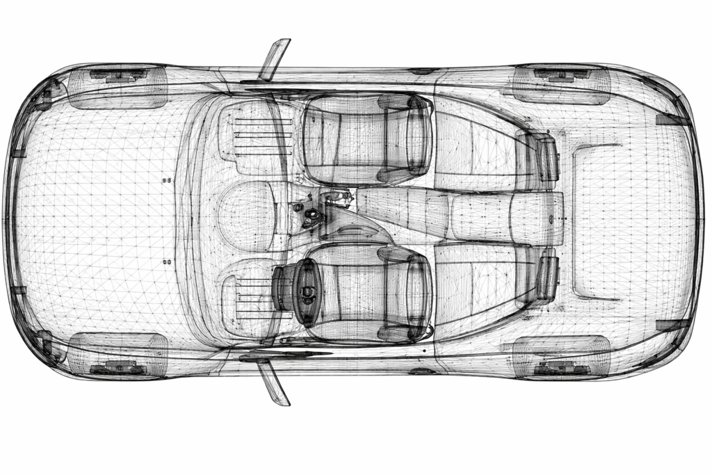
Vehicle packaging defines spatial architecture and multidisciplinary integration.
High-quality CAD directly affects:
• Occupant ergonomics
Seat placement, steering wheel reach, visibility, and H-point definition.
• Subsystem spatial feasibility
Powertrain envelopes, battery pack boundaries, and cooling module stacking.
• Thermal and electrical routing feasibility
HVAC, harness paths, cooling loops, and exhaust routing.
• ADAS sensor visibility
Radar fields, camera placement, LiDAR line-of-sight.
Poor CAD leads to packaging clashes, non-compliance with safety regulations, and multiple NPD delays.
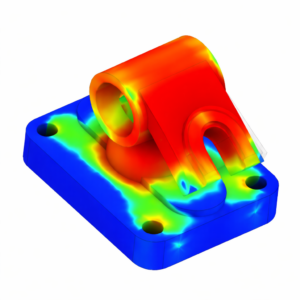
CAE analysts rely heavily on CAD quality because:
4.1 Meshing Efficiency
• Clean surfaces → higher-quality meshes
• Proper topology → lower element distortion
• Simplified geometry → reduced solve time
4.2 Simulation Validity
• CAD errors propagate into simulation error
• Feature inconsistencies generate poor stress paths
• Dimensional inaccuracy results in unrealistic crash deformation
4.3 Multi-Physics Fidelity
Thermal, NVH, durability, modal, stiffness, and crash simulations all depend on the fidelity of CAD.
4.4 Optimization & AI-driven Design
Topology optimization, generative design & DOE require consistent CAD models with load paths aligned to real geometry.
Manufacturing feasibility begins at the CAD stage
5.1 Tooling & Die Design
• The stamping, forging, and casting dies are generated directly from CAD.
• Any inaccuracies cause material wrinkles, spring-back issues, or poor forming performance.
5.2 Assembly & Welding Fixtures
CAD determines:
• Locating pins
• Weld guns paths
• Clamping strategy
• Accessibility for automation
5.3 Injection Molding & Casting
• Draft analysis
• Parting line definition
• Cooling channel integration
• Rib & boss optimization
5.4 Tolerance Stack-Up and Dimensional Control
• Dimensional variations propagate across the vehicle
• CAD controls GD&T, gap & flushness, fit & finish
Manufacturing rejects, assembly failures, and tooling rework are direct consequences of inadequate CAD integrity.
Customer perception is strongly influenced by visible geometry:
6.1 Exterior Aesthetics
• Surfacing quality
• Reflection behavior
• Belt-line continuity
6.2 Interior Fit & Finish
• Gap & flushness targets (±0.5 mm precision)
• Seam alignment
• Tactile design interactions
6.3 Craftsmanship Indicators
• Symmetry of controls
• Integration of trim elements
• Visibility of fasteners & shut faces
High-quality CAD ensures that these parameters are engineered, not discovered during prototype builds
Critical safety systems are fully geometry-dependent:
7.1 Crashworthiness CAD Requirements
• Crash load paths
• Controlled deformation zones
• Airbag deployment envelopes
• Steering column collapse strategies
7.2 Homologation
CAD is evaluated against global standards:
• FMVSS
• ECE
• GTR
• AIS
• Pedestrian head impact geometry
• Lighting mounting heights & visibility cones
7.3 Battery Safety for EVs
• Firewalls
• Thermal propagation paths
• Cell isolation barriers
A deficient CAD model risks regulatory failure and major re-engineering costs.
High-quality CAD is crucial to digital continuity:
• PLM traceability
Revisions, variants, options, and part history.
• Digital Twin accuracy
Real-time control models and vehicle simulations rely on geometry fidelity.
• End-to-end NPD automation
Workflow scripts, simulation automation, and BOM generation depend on correct CAD structuring.
Optimization is impossible without accurate CAD:
• Material reduction
Topology-driven design
Section thinning
Rib optimization
• Weight targets
BIW lightweighting
Aluminum/steel hybrid structures
Composite integration
• Cost efficiency
Part consolidation
Tool simplification
Manufacturing-friendly geometry
High-quality CAD enables design engineers to achieve aggressive targets reliably.
In the automotive industry, high-performance engineering begins with high-quality CAD. It is the single, unifying technical dataset that drives:
• Simulation accuracy
• Vehicle packaging feasibility
• Manufacturing and assembly success
• Crash and safety compliance
• Aesthetic quality and brand identity
• Cost, weight, and performance optimization
• Digital continuity and future platform scalability
A strong CAD foundation reduces NPD cycle time, eliminates rework, improves manufacturing efficiency, and ensures that the vehicle performs exactly as designed.