An engineering-first guide for design, selection and system integration.
Electric motors are the fundamental energy-conversion device in EVs, and for small and mid-size electric vehicles, they become a systems-level constraint rather than a modular commodity. Packaging, mass, thermal headroom, efficiency across real drive cycles, NVH, manufacturability and cost must all be balanced.
Selecting the right motor, therefore, requires more than matching peak power numbers. It requires a repeatable engineering workflow that ties vehicle requirements to electromagnetic, thermal and control realities.
This article walks an experienced EV engineer through that workflow, emphasizes the critical physics and trade-offs in EV traction motor design, and gives practical rules and checks for electric motor selection for EVs.
Expect equations where they help, practical mitigation strategies, and integration checkpoints that will save costly rework down the line.
Motor selection must begin with the vehicle, not a vendor catalogue.
Start by deriving the required longitudinal traction force at the wheel for the relevant use cases (launch, gradeability, cruising, overtakes).
The wheel torque requirement is then:
where is the wheel radius and motor torque Tm relates through drivetrain reduction and efficiency:
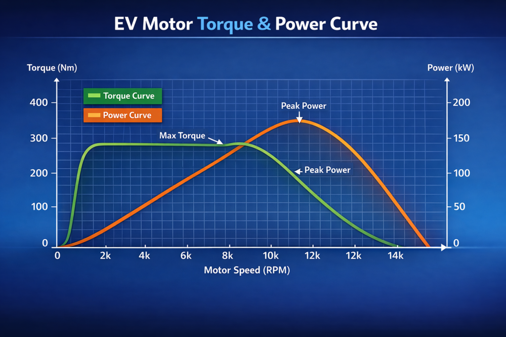
This produces a torque–speed envelope (torque vs rotor speed) that the motor must meet continuously (not only peak). Use target drive cycles (EPA/FTP, WLTP, or representative urban/highway profiles) to derive the working islands of duty (frequent low-speed bursts, sustained cruise and repeated regenerative braking).
Why this matters: Sizing a motor for peak 0–60 time without checking continuous torque during a 20-minute hill climb or an extended highway run leads to a selection that will overheat or consume unacceptable energy.
Basic relations useful for quick sanity checks:
VbackEMF=ke⋅ω
where is the back-EMF constant (V/(rad/s)). The inverter’s available DC bus voltage and switching strategy determine the maximum achievable electrical speed (hence mechanical base speed) before field weakening is required. Field weakening injects d-axis current to reduce effective back-EMF and extend speed, but it increases losses and reduces torque capability.
Engineers must connect three domains:
A simple selection heuristic is that if the desired base speed (wheel speed × gear ratio) yields back-EMF near the inverter voltage at required continuous torque, you will need aggressive field weakening during cruise → plan cooling and accept efficiency loss.
Permanent Magnet Synchronous Motors (PMSM)
For small/mid vehicles where packaging and range dominate, PMSMs are the default. Key decisions include surface-mounted (SPM) vs. interior (IPM). IPM offers saliency that aids field weakening and higher continuous power at elevated speeds, so SPM is simpler and slightly denser torque-wise.
Induction Motors (IM)
IMs remain attractive where magnet sourcing risk is unacceptable and where inverter and thermal systems can handle rotor losses.
Switched Reluctance Motors (SRM)
SRMs are promising for industrial EVs and niche applications, but for customer cars that demand refinement, they require significant system mitigation.
Axial flux motors are an option where extreme torque density and short stack length are needed, but they bring thermal and mechanical packaging complexities.
Peak power metrics (kW) and specific power (kW/kg) are attractive but misleading. Real-world performance is driven by the motor’s efficiency map across torque and speed. A high-power, high-speed motor optimized for peak output will often run off its peak efficiency on everyday cycles, increasing battery draw and thermal stress.
An actionable rule is to compare candidates by weighted drive-cycle efficiency (energy consumed over a representative cycle), not peak efficiency. Use a quasi-steady drive cycle simulation to produce a scalar “drive-cycle energy multiplier” to compare motors.
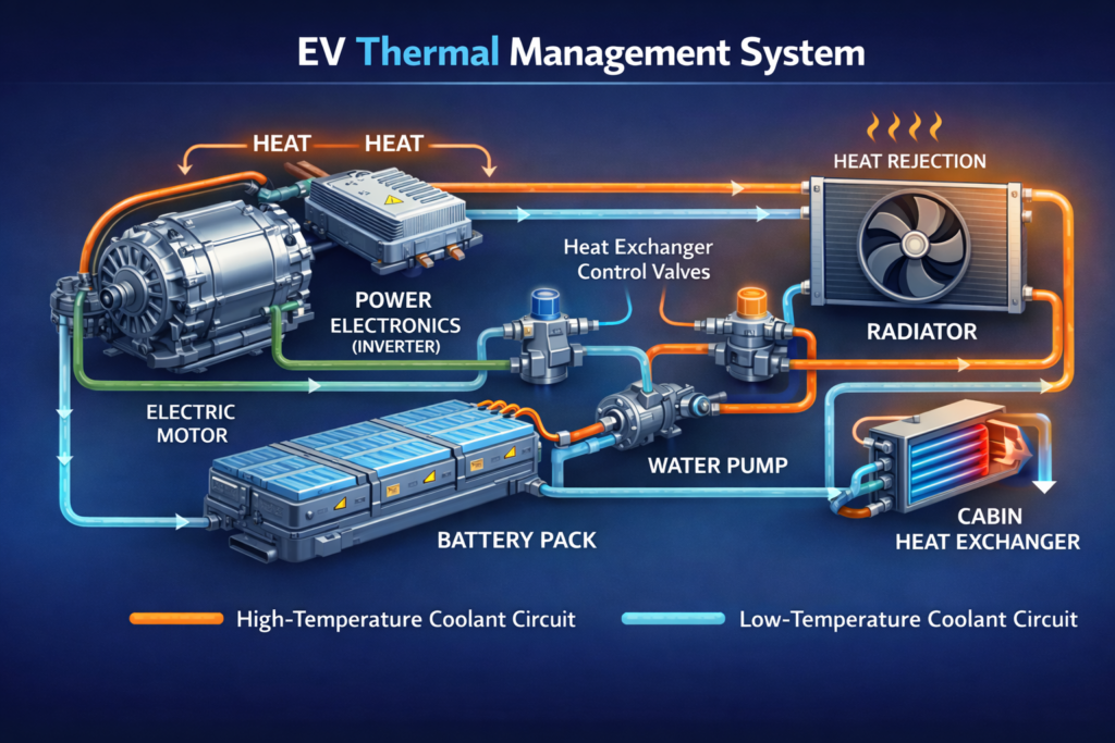
Thermal limits (insulation class, magnet Curie temperature, bearing lifetime) typically cap continuous torque long before electromagnetic limits do.
Common cooling approaches:
Design so the motor has time to cool down. It can handle short bursts of high power, as long as you give it enough cooling time afterwards. Always verify continuous torque at steady-state stator temp and derate accordingly. Include inverter thermal coupling when performing continuous power budgets.
Practical levers available to designers and engineers:
Use finite element analysis (FEA) to quantify torque ripple, losses (copper, iron, eddy in magnets), and thermal hotspots before hardware.
Motor and inverter are an electromechanical pair, so choosing one without the other risks a cascade of problems.
Key interactions:
When specifying a motor, include inverter limits (Vdc, Imax, switching freq), expected control algorithms and any closed-loop requirements (encoder resolution, latency).
EVs lack engine masking, so the motor NVH is therefore highly visible. Sources:
Mitigations:
Include NVH objectives early, as late fixes are expensive.
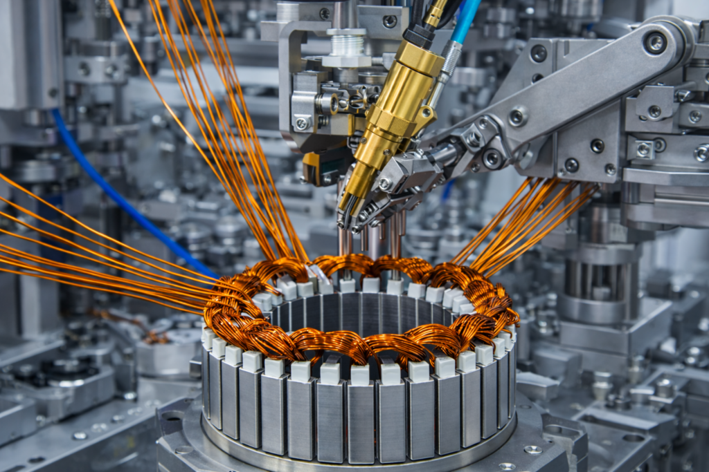
Engineering design must be manufacturable at scale. Consider:
Design for yield so that modest reductions in test failure rate can produce large unit cost savings over production volumes.
Plan these validation steps before SOP:
The lifecycle viewpoint (insulation class, magnet life, bearing wear, control update path) prevents warranty surprises.
Conclusion – Choose With System Thinking
For small and mid-size electric vehicles, motor selection is a multi-axis optimisation problem. The right motor is not the smallest or the one with the highest peak power. Instead, it is the one that best aligns with the vehicle’s torque–speed envelope, thermal architecture, inverter capability, NVH targets and manufacturability constraints.
Approach selection as EV traction motor design work to quantify vehicle demands, model losses and thermal limits, co-design with inverter and controls, validate with multiphysics simulation and dyno testing, and bake manufacturability into the design early.
Doing so reduces late changes, improves range and reliability, and ensures the vehicle performs as promised in the hands of real drivers.
If you want to turn a torque-speed envelope into dyno-validated, production-ready hardware, AESGS can help.
AES provides end-to-end EV engineering support, from EV systems and motor–inverter co-design to CAE-driven simulation, embedded controls and production validation, all delivered with onshore–offshore technical teams.
See recent case studies and projects that demonstrate prototype-to-commissioning delivery, and use those learnings to de-risk your motor selection and validation program.
Ready to start a motor-inverter co-design or request a vendor-agnostic spec sheet?
Contact AESGS to discuss your vehicle targets and test requirements, we’ll help translate your system requirements into validated motor hardware and a repeatable production process.